
Product Introduction
· The ACF series activated carbon adsorption tower can be fabricated from materials such as SS41, SUS304 and PP. The interior of the tower body must undergo anti-corrosion treatment, while the exterior is equipped with sufficient reinforcement to bear the load required for system operation.
· The adsorption medium adopts high-quality coconut shell or coal-based activated carbon cylindrical particles. Its main component is carbon element. Compared with other adsorption media, it has a large specific surface area (900~2200 m²/g), a porosity of ≥ 80% and uniform pore size (about 20 A).
· As an adsorption medium, activated carbon has a good adsorption effect on various VOC waste gases. It also has the advantages of high adsorption universality, fast adsorption speed, low adsorption resistance, easy regeneration and convenient replacement.
· The ACF series activated carbon adsorption tower is usually horizontal in appearance and adopts a top-feeding and bottom-unloading design. It is equipped with an inspection platform and a ladder, making the later maintenance and replacement work very convenient and safe.
· Compared with other treatment equipment, the ACF series activated carbon adsorption tower has a lower initial investment cost. Since activated carbon is used as the adsorption medium, the failure rate of system operation is almost zero. The main power consumption of the system only comes from the fan, so the system operation cost is also more economical.
· The perfect combination of economy, practicality and high efficiency makes the ACF series activated carbon adsorption tower an effective adsorption device for VOCs, and it has become the preferred environmental protection equipment for most customers in the current market.
Selection of ACF Activated Carbon Adsorption Tower
· Determine the parameters such as composition, temperature, humidity and concentration of each VOC waste gas;
· Design the gas collecting hood and calculate the air volume parameters of the system according to the results of on-site survey and measurement;
· Select the equipment model with reference to the designed air volume;
· Determine the system pressure loss, fan selection, automatic control and other aspects;
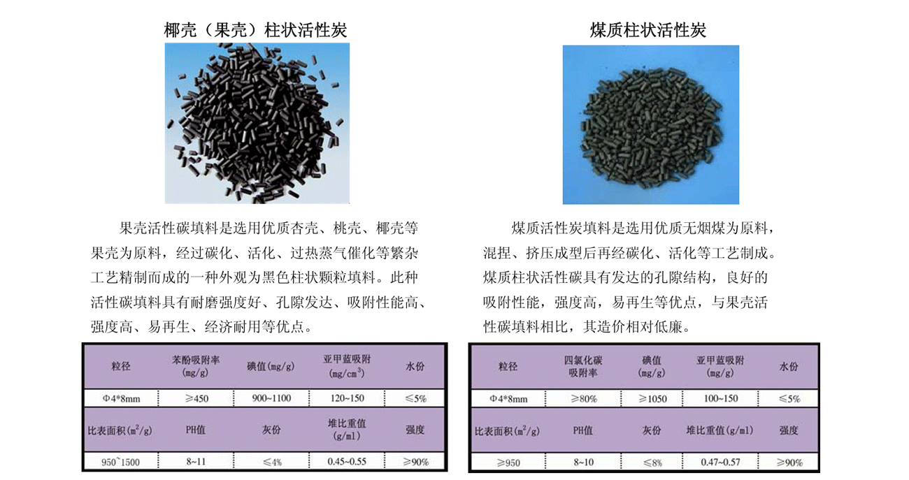
Selection of Special Activated Carbon Fillers for ACF
Specifications
| Model | Air Handling CapacityQ(CMM) | A(mm) | B(mm) | C(mm) | D(mm) | E(mm) | F(mm) | Activated Carbon Dosage(T) |
| ACF-01 | 50~70 | 2150 | 2000 | 2200 | ∅350 | ∅350 | 400*500 | 0.5 |
| ACF-02 | 20~30 | 3100 | 2000 | 2500 | ∅500 | ∅500 | 400*500 | 1 |
| ACF-03 | 30~50 | 3600 | 2000 | 2800 | ∅650 | ∅650 | 400*500 | 1.5 |
| ACF-04 | 50~80 | 3900 | 2000 | 3000 | ∅750 | ∅750 | 400*500 | 2 |
| ACF-05 | 80~110 | 4100 | 2000 | 3400 | ∅850 | ∅850 | 400*500 | 2.5 |
| ACF-06 | 120~150 | 4400 | 2000 | 3600 | ∅900 | ∅900 | 400*500 | 3 |
| ACF-07 | 150~180 | 4900 | 2000 | 4000 | ∅1000 | ∅1000 | 400*500 | 4 |
| ACF-08 | 180~240 | 5500 | 2000 | 4200 | ∅1200 | ∅1200 | 400*700 | 5 |